Metal core or IMS (Insulated Metallic Substrate) circuit boards are an excellent alternative to standard circuit boards, if the circuit boards are exposed to large mechanical loads, or a high level of dimensional stability is required, or high temperatures must be conducted away from power components or LEDs. Benefit from our many years of experience with Insulated Metal Substrate (IMS) PCBs.
Metal core circuit boards

The thermal conductivity assisted by the aluminium core in the circuit boards enables higher packing density, more stable operating parameters, higher operational safety and a reduced failure rate. Ideal e.g. for laser diodes!
The integration of the cooling unit in the printed circuit board also results in space savings.
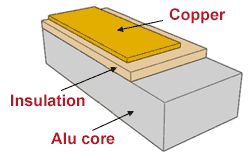
Additional application areas for this technology include: high current application, power LED's, SMD and power circuit boards. The high thermal conductivity and small insulation thickness (standard: 100µm) permits a quick and effective transfer of the heat produced.
In addition, Multi-CB is also at your side for further aspects of thermal management:
- Design / construction of the heat-critical circuit board
- Thermal via array
- Thick-Copper PCBs
Always included
- Alu core 1.5mm, 35µm Cu
- 2.0 W/mK Thermal conductivity
- 100µm Insulation thickness
- Surface HAL lead-free
- 1x solder-stop white
- Milling inner / outer
- V-Scoring (clean & simple)
- E-Test, Design Rule Check
Available types
1 layer IMS PCB
You can order single sided, double sided and double sided pth aluminium core circuit boards from Multi-CB (see: layer buildup). Depending on the design, the thermal conductivity ranges from 1.0 to 7.0 W/mK (the value for FR4 is approx. 0.3 W/mK).
The option Z-axis milling of the insulation also allows a direct connection of the components to the aluminum core by means of thermal paste (or similar). Bendable metal core printed circuit boards with ceramic-based insulation can also be produced.
Technical options for Metal core circuit boards
| Options | Inklusive | Notes | |||||
|---|---|---|---|---|---|---|---|
| Material | Options | Aluminium core | Inklusive | - | Notes | Data sheets | |
| Max. size | Options | 420mm x 570mm | Inklusive | - | Notes | ||
| Design | Options | 1 layer, 2 layers plated-through | Inklusive | Notes | |||
| Aluminium thickness | Options | 0.5mm, 0.8mm, 1.0mm, 1.5mm, 2.0mm | Inklusive | 1.5mm | Notes | ||
| Copper | Options | 35µm, 70µm, 105µm, 140µm | Inklusive | 35µm | Notes | ||
| Insulation thickness | Options | 75µm, 100µm, 125µm, 150µm | Inklusive | 100µm | Notes | ||
| Thermal conductivity | Options | 2.0W/mK - 7.0W/mK | Inklusive | 2.0W/mK | Notes | ||
| Conductor width min. | Options | 150µm | Inklusive | 150µm | Notes | ||
| Annular ring min. | Options | 125µm | Inklusive | 150µm | Notes | ||
| Drill (NPTH) min. Ø | Options | 0.5mm | Inklusive | 0.9mm | Notes | Design-Aid | |
| Via min. Ø | Options | 0.2mm | Inklusive | 0.2mm | Notes | ||
| Surface | Options | HAL lead-free, chemical gold | Inklusive | HAL lead-free | Notes | Surfaces | |
| Solder-stop | Options | white, black, green, red, blue | Inklusive | white, black | Notes | ||
| Legend print | Options | black, white | Inklusive | - | Notes | ||
| Milling | Options | yes | Inklusive | yes | Notes | ||
| V-Scoring | Options | yes | Inklusive | yes | Notes | clean & simple | |
| Z-Axis milling | Options | yes | Inklusive | - | Notes | ||
| RoHS compliant | Options | yes | Inklusive | yes | Notes | ||
| UL-certified | Options | yes | Inklusive | yes | Notes | UL certificate |
1 Lage Metal core
Design Parameters
| 35µm Cu | 70µm Cu | ||||
|---|---|---|---|---|---|
| Min. conductor width | 35µm Cu | 150µm | 70µm Cu | 200µm | |
| Min conductor spacing | 35µm Cu | 150µm | 70µm Cu | 200µm | |
| Min. annular ring | 35µm Cu | 125µm | 70µm Cu | 200µm | |
| Min. drill (NPTH) | 35µm Cu | 0.7mm | 70µm Cu | 0.7mm | |
| Min. drill spacing | 35µm Cu | 250µm | 70µm Cu | 250µm |
1 layer Metal core - Material
| Material for metal core boards 1 Layer |  Thermal conductivity Thermal conductivity |  Thermal resistance Thermal resistance |  Surface resistivity Surface resistivity |  Dielectric glass transition Dielectric glass transition |  Dielectric Breakdown (AC)* Dielectric Breakdown (AC)* |  CTI CTI | |||||||
|---|---|---|---|---|---|---|---|---|---|---|---|---|---|
| Material for metal core boards 1 Layer | Thermal conductivity | W/mK | Thermal resistance | K/W | Surface resistivity | MΩ | Dielectric glass transition | °C | Dielectric Breakdown (AC)* | kV | CTI | PLC | |
| Material for metal core boards 1 Layer | TC-Lam 2.0 | Thermal conductivity | 2.0 | Thermal resistance | 0.50 | Surface resistivity | 10^7 | Dielectric glass transition | 100 | Dielectric Breakdown (AC)* | 5.0 | CTI | 0 |
| Material for metal core boards 1 Layer | HA50 (3) | Thermal conductivity | 2.2 | Thermal resistance | 0.41 | Surface resistivity | 10^6 | Dielectric glass transition | 120 | Dielectric Breakdown (AC)* | 4.3 | CTI | 0 |
| Material for metal core boards 1 Layer | AL-200 | Thermal conductivity | 2.0 | Thermal resistance | 0.35 | Surface resistivity | 10^8 | Dielectric glass transition | - | Dielectric Breakdown (AC)* | 3.5 | CTI | 0 |
| Material for metal core boards 1 Layer | AL-300 | Thermal conductivity | 3.0 | Thermal resistance | 0.30 | Surface resistivity | 10^8 | Dielectric glass transition | - | Dielectric Breakdown (AC)* | 3.5 | CTI | 0 |
| Material for metal core boards 1 Layer | Ventec VT-4B3 Ceramic Filled | Thermal conductivity | 3.0 | Thermal resistance | - | Surface resistivity | 5 x 10^8 | Dielectric glass transition | 130 | Dielectric Breakdown (AC)* | 8.0 | CTI | 0 |
| Material for metal core boards 1 Layer | Ventec VT-4B4 Ceramic Filled | Thermal conductivity | 4.2 | Thermal resistance | - | Surface resistivity | 2 x 10^7 | Dielectric glass transition | 120 | Dielectric Breakdown (AC)* | 8.0 | CTI | 0 |
| Material for metal core boards 1 Layer | Ventec VT-4B7 Ceramic Filled | Thermal conductivity | 7.0 | Thermal resistance | - | Surface resistivity | 2 x 10^7 | Dielectric glass transition | 100 | Dielectric Breakdown (AC)* | 8.0 | CTI | 0 |
* Examples for 100μm dielectric or 80μm for CCAF material
2 layers Metal core (PTH) - Design Parameters
Design Parameters
| 35µm Cu | 70µm Cu | ||||
|---|---|---|---|---|---|
| Min. conductor width | 35µm Cu | 150µm | 70µm Cu | 200µm | |
| Min conductor spacing | 35µm Cu | 150µm | 70µm Cu | 200µm | |
| Min. annular ring | 35µm Cu | 125µm | 70µm Cu | 200µm | |
| Min. drill(NPTH) | 35µm Cu | 0.7mm | 70µm Cu | 0.7mm | |
| Min. via (PTH) | 35µm Cu | 0.3mm | 70µm Cu | 0.3mm | |
| Min. drill spacing | 35µm Cu | 250µm | 70µm Cu | 250µm | |
| Min. via spacing | 35µm Cu | 300µm | 70µm Cu | 300µm | |
| Aspect ratio | 35µm Cu | 10:1 | 70µm Cu | 10:1 |
2 layers Metal core (PTH) - Material
| Material for metal core boards 2 Layers (plated-through) | Thermal conductivity | Thermal resistance | Surface resistivity | Dielectric glass transition | Dielectric Breakdown (AC)* | CTI | |||||||
|---|---|---|---|---|---|---|---|---|---|---|---|---|---|
| Material for metal core boards 2 Layers (plated-through) | Thermal conductivity | W/mK | Thermal resistance | K/W | Surface resistivity | MΩ | Dielectric glass transition | °C | Dielectric Breakdown (AC)* | kV | CTI | PLC | |
| Material for metal core boards 2 Layers (plated-through) | Ventec VT-4A2 | Thermal conductivity | 2.2 | Thermal resistance | - | Surface resistivity | 2 x 10^7 | Dielectric glass transition | 130 | Dielectric Breakdown (AC)* | 7.5 | CTI | 0 |
| Material for metal core boards 2 Layers (plated-through) | Ventec VT-4B3 Ceramic Filled | Thermal conductivity | 3.0 | Thermal resistance | - | Surface resistivity | 5 x 10^8 | Dielectric glass transition | 130 | Dielectric Breakdown (AC)* | 8.0 | CTI | 0 |
* Examples for 100μm dielectric or 80μm for CCAF material
Overview of technical options for special production circuit boards.
For optimal preparation, we recommend that you contact our CAM-Station engineers early on. We would be very happy to advise you during the development process.
UL certification for Metal core circuit boards
At Multi-CB, you also get Metal core circuit boards with UL certification.