Metal core / IMS

IMS  PCB doublesided plated-through (PTH)

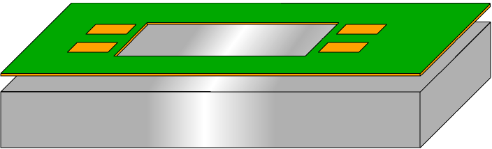
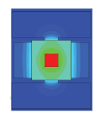
At Multi-CB you can get aluminium core PCBs with a thermal conductivity of 1.0 W/mK to 8 W/mK. The aluminium core helps to distribute the selective heat of heat-intensive components and to make the heat development on the printed circuit board more homogenous. The rule of thumb for many high-power LEDs is: A 10° C lower junction temperature increases the lifetime by 10.000h.

For one-sided metal core PCBs, a heat sink and/or fan (active cooling) can be mounted directly on the aluminum (passive cooling).

Design parameters

NPTH-drills - Metal core

PCB thicknessMin. drill diameter
PCB thickness0.5mm Metal coreMin. drill diameter0.7mm (o.r. 0.5mm)
PCB thickness0.8mm Metal coreMin. drill diameter0.7mm
PCB thickness1.0mm Metal coreMin. drill diameter0.8mm
PCB thickness1.5mm Metal coreMin. drill diameter0.9mm
PCB thickness2.0mm Metal coreMin. drill diameter1.0mm

1 layer Metal core

 35µm Cu70µm Cu
 Min. conductor width35µm Cu150µm70µm Cu200µm
 Min conductor spacing35µm Cu150µm70µm Cu200µm
 Min. annular ring35µm Cu125µm70µm Cu200µm
 Min. drill (NPTH)35µm Cu0.7mm70µm Cu0.7mm
 Min. drill spacing35µm Cu250µm70µm Cu250µm

2 layers Metal core (plated-through)

 35µm Cu70µm Cu
 Min. conductor width35µm Cu150µm70µm Cu200µm
 Min conductor spacing35µm Cu150µm70µm Cu200µm
 Min. annular ring35µm Cu125µm70µm Cu200µm
 Min. drill(NPTH)35µm Cu0.7mm70µm Cu0.7mm
 Min. via (PTH)35µm Cu0.3mm70µm Cu0.3mm
 Min. drill spacing35µm Cu250µm70µm Cu250µm
 Min. via spacing35µm Cu300µm70µm Cu300µm
 Aspect ratio35µm Cu10:170µm Cu10:1

Z-axis milling

To bond components directly to the aluminium with thermal compound, Z-axis milling (depth milling) can be used. The isolation / prepreg is removed in this area.


Metal core Z-axis milling / depth milling

Thermal conductivity

The given thermal conductivity W/mK always refers to the insulation layer (prepreg) between copper and aluminium.

Typical Thermal conductivity figures

MaterialThermal conductivity
MaterialCopperThermal conductivity380 W/mK
MaterialAluminiumThermal conductivity140 – 220 W/mK
MaterialPrepregThermal conductivity1 – 8 W/mK

Isolation / Prepreg

The thinner the insulation layer is chosen, the lower the thermal resistance (= better overall thermal resistance). However, it also reduces the breakdown voltage.

Exemplary breakdown voltage – Material Ventec VT-4A1

Prepreg thicknessDielectric breakdown (AC)
Prepreg thickness75µmDielectric breakdown (AC)6.0kV
Prepreg thickness100µmDielectric breakdown (AC)7.5kV
Prepreg thickness125µmDielectric breakdown (AC)9.0kV
Prepreg thickness150µmDielectric breakdown (AC)10kV

Heat development - example

The following is a comparison of the heat development on different PCB types. Conducted by OSRAM using an OSLON © SSL high-power LED (1W, 3.2V, 350mA), ambient temperature: 25° C.

 FR4 1LayerFR4 max. padsFR4 Thermal ViasMetal core 1Layer
  FR4 1LayerHeat development FR4 PCBFR4 max. padsHeat development FR4 PCB with max. PadsFR4 Thermal ViasHeat development FR4 PCB with Thermal ViasMetal core 1LayerHeat development Metal core IMS PCB
 ConstructionFR4 1LayerFR4 0.8mm, 35µm CuFR4 max. padsFR 0.8mm, 35µm Cu, max. pad sizeFR4 Thermal ViasFR4 0.8mm, 70µm Cu, w. Thermal ViasMetal core 1LayerAluminium core 1.5mm, 2.2 W/mK, Isolation 75µm
 Heat conduction Cu
Heat development FR4 PCB  scale
FR4 1LayerHeat development FR4 PCB thermicFR4 max. padsHeat development FR4 PCB with max. pads thermicFR4 Thermal ViasHeat development FR4 PCB with Thermal Vias thermicMetal core 1LayerHeat development Metal core IMS PCB thermic
 Thermic resistance RthFR4 1Layer45 K/WFR4 max. pads28 K/WFR4 Thermal Vias8 K/WMetal core 1Layer3 K/W
 Junction temperature riseFR4 1Layer53°CFR4 max. pads35°CFR4 Thermal Vias15°CMetal core 1Layer10°

Optional

You can get UL Certified Metal core Printed Circuit Boards from Multi-CB.

In addition, we also offer flexible Metal core PCBs. The prepreg is in this case filled with ceramics (instead of glass). Material e.g. Ventec VT-4B1.